Materials Processing
Laser marking is a process that selectively changes the surface color of a material using a laser while generally leaving the underlying material unaffected. Examples include adding QR codes or text to a material without introducing recesses features.
Laser etching is similar to laser marking, but the laser causes physical melting and, in some cases, expansion of the material. In contrast to laser marking, laser etching can produce slightly recessed or raised features and does impact material below the surface of the substrate. Quick, low-cost, high-contrast barcodes, serial numbers and logos are examples. Laser removal of sapphire used in manufacturing display circuitry is a more advanced application example.
Laser engraving is similar to laser etching, but instead of melting the substrate, it uses higher energies to vaporize the material. This causes a physical removal of material and produces durable deep engraved features which can also be used for barcodes, serial numbers, etc.
Laser cutting uses a very focused continuous laser to cut intricate shapes into a substrate. Unlike marking, etching, and engraving, laser cutting cuts entirely through a material. Examples include cutting medical grade endoscope tips or cleanly trimming automotive material edges - deburring may be required in some cases. Speed can be increased with power and decreased for higher precision.
Laser welding uses a pulsed laser beam to durably and reliably fill the minimal gap between two (possibly dissimilar) materials. Minimizing overheating, porosity, cracking, and gaps while maintaining appropriate pull strength are important to quality and high yields.
Laser ablation is the process of applying high intensity light to a substrate to remove or destroy surface material. Examples include removing rust off of metallic parts for maintenance or removing target tissues in biomedical applications (such as scar tissue or cancerous cells).
Materials Processing – Laser Use Examples
Categorized by Electromagnetic Spectrum Region
UV | ✓ Cut, mark and weld assorted materials, especially glass or heat-sensitive materials ✓ Laser cut with continuous wave excimer laser (~10 - 500 W) ✓ Precision mark with UV pulsed laser (~3 - 30 W) ✓ Laser weld with UV pulsed laser (~5 - 30 W) |
Visible | ✓ Cut, mark, weld assorted materials ✓ Laser cut with Diode (~1 - 100 W) CW laser ✓ Laser weld at low power using green lasers, known for precision (for example, laser weld copper) |
Near Infrared (NIR) & Infrared (IR) | ✓ Cut, Debur, Engrave, Etch, Mark, Anneal, Weld ✓ Laser cut with YAG CW (~200 - 6000 W), fiber CW or CO2 CW (~30,000 - 40,000 W) lasers ✓ Debur with fiber CW laser ✓ Laser mark with YAG CW or pulsed* (~up to 1000 W / *~250 MW), or pulsed fiber ✓ Engrave, etch, anneal, with fiber pulsed laser ✓ Laser weld with fiber pulsed (~20 - 1000 W), CO2 pulsed (~10 - 150 W), nanofiber pulsed for disimilar material, or YAG pulsed microwelds of electronic connections and spot welds |
Materials Processing – Important Beam Parameters
Intensity
Irradiance Fluence Continuous & Pulsed |
Adequate beam intensity distribution means sufficient energy transfer to the material. This can result in process repeatability, higher quality parts, and fewer defects. It should yield proper and predictable cutting, etching, engraving, marking, welding and ablation at the correct location, depth, speed and surface finish. The wrong amount of irradiance or fluence could mean challenges including material damage, incomplete cuts, welds or marks and an assortment of other defects causing poor quality, scrap, and lost time. Regular beam profiling can help minimize these challenges. The 2D beam profile to the left shows a Gaussian beam intensity profile where the intensity is greatest at the center, white, and decreases moving outward toward the outer circumference, blue. Profiles like this give relative information about the intensity distribution. For other beam shape profiles used in materials processing, see beam shape, below. The power applied at the beam waist divided by the spot size also gives information about the power intensity (for continuous beams). Common laser power levels used in materials processing vary greatly considering the many laser processes. Some examples:
Note - For a continuous beam, the terms intensity, irradiance or power density are used: power divided by area, W/cm². For a pulsed beam, the term fluence or energy density is used: energy divided by area, J/cm². A pulse, repeated at the pulse frequency, will have peak irradiance and maximum pulse energy values reached during the pulse. |
Beam Waist Spot Size Focus |
At the focus, the beam diameter reaches a minimum, often referred to as the spot size or beam waist diameter. Focusing a beam to a smaller spot size will increase the density in that spot and vice versa. It is important to apply the optimal amount of power or energy at the specified spot size. Too large or too small will affect the desired target location and may lead to some of the defects mentioned previously. Some common spot size values in materials processing vary from ~20 µm – mm+. Example spot sizes:
|
Focal Plane Focal Distance |
The focal plane of a non-collimated laser beam is generally where the beam is focused to its smallest spot size. The focal distance is the distance from the focusing lens along the axis of propagation to the focal plane and can vary depending on the presence of other optics: the laser source, focusing optics and possible beam shaping devices. The focal plane, in many cases, lines up exactly with the material surface or working plane, but may be offset, examples below:
|
Beam Shape
|
Common shapes:
Beam profilers provide a quick and effective means to quantify the relative intensity distribution of a beam to verify beam shape. |
Beam Propagation |
Beam propagation is the behavior of a laser beam propagating through free space and is described by M² (beam quality), divergence and pointing. M² characterizes how close a power intensity profile is to a “Gaussian” beam and can give a sense of how focused the beam is. Laser cutting is an example where a more focused beam is important, so lower M² values are desirable.
Divergence describes the angle the beam diverges outward from the beam waist into the far field, much beyond the Rayleigh length. In contrast, divergence near zero is a way to confirm a beam is collimated, for example before being focused. This helps to ensure that once the beam is focused, it will be at the correct spot size and location. Pointing is the angle of laser beam propagation with respect to the optical axis. A pointing value of zero means it is perfectly aligned with the optical axis. It characterizes how much a laser stays on center as it gets farther from the laser source, including accuracy and precision. Pointing measurements support better beam alignment. Misalignments can be caused by thermal fluctuations in the environment or in the laser system of high power lasers, as well as due to attenuation and time. |
Have questions or need help identifying the right solution for your application?

Related Products

TaperCamD-LCM
- Large 25 x 25 mm active area
- Suitable for large beam profiling

WinCamD-LCM
- Versatile global shutter supports CW & pulsed beams
- 355 to 1150 nm standard with UV, 1310 nm, and 1550 nm options
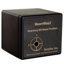
BeamMap2
- Robust, multi-plane beam profiling
- Real-time M², divergence, pointing, and focal measurements

BladeCam2-XHR
- Compact, affordable beam profiling
- Ultra-small 3.2 µm pixels
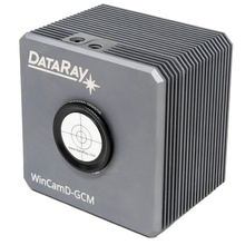
WinCamD-GCM
- GigE Vision supports long cable runs (to 100 m)
- Access your profiler via ethernet network