Additive Manufacturing
Considered a disruptive technology, additive manufacturing advantages include increased geometrical freedom, lighter individual parts instead of assemblies, greater ease with customized parts, less material usage and waste, and the associated efficiencies. In aerospace, for example, metal 3D printed jet engine parts can be made with complex internal channels and cooling systems, thereby improving efficiency and performance.
Limitations of this growing technology have been cost, time and part quality including surface quality. However, additive manufacturing breakthroughs are being made constantly, with one hybrid solution incorporating both additive and subtractive manufacturing processes.
Metal additive manufacturing processes, such as Power Bed Fusion (PBF), Selective Laser Sintering/Melting (SLS/SLM), and Laser/Direct Metal Deposition (LMD/DMD) generally require precise control of lasers parameters for good results, including beam size, shape, and alignment. While the specific methodology for each technique varies from method to method, utilizing beam profiling systems to monitor beam parameters leads to higher quality results with greater repeatability.
Additive Manufacturing – Laser Use Examples
Categorized by Electromagnetic Spectrum Region
Visible | ✓ Melt copper with diode-pumped solid state (DPSS) pulsed green lasers (~50 - 500 W+) |
Near Infrared (NIR) & Infrared (IR) | ✓ Fusion of metal powder bed using continuous wave fiber lasers (~100 - 1000 W) ✓ SLS of polymers using continuous wave CO2 laser (~20 - 100 W) |
Additive Manufacturing – Important Beam Parameters
Intensity
Irradiance Fluence Continuous & Pulsed |
Adequate beam intensity distribution means sufficient energy transfer to the material. This can result in process repeatability, higher quality parts, and fewer defects. Poor distribution can mean challenges like difficulty controlling melt area, incomplete or excessive melting or bonding, compromised structural integrity and strength, undesirable porosity, keyholing, vaporization and surface defects. Regular beam profiling can help minimize these challenges. The 2D beam profile to the left shows a Gaussian beam intensity profile where the intensity is greatest at the center, white, and decreases moving outward toward the outer circumference, blue. Profiles like this give relative information about the intensity distribution. For other beam shape profiles used in additive manufacturing, see beam shape, below. The power applied at the beam waist divided by the spot size also gives information about the power intensity (for continuous beams). Common additive manufacturing laser power ranges: ~100 - 1000 W+. Note — For a continuous beam, the terms intensity, irradiance or power density are used: power divided by area, W/cm². For a pulsed beam, the term fluence or energy density is used: energy divided by area, J/cm². A pulse, repeated at the pulse frequency, will have peak irradiance and maximum pulse energy values reached during the pulse. |
Beam Waist Spot Size Focus |
In additive manufacturing, it is common for the work piece to be located at the focal plane of a focused laser. At the focus, the beam diameter reaches a minimum, often referred to as the spot size or beam waist diameter. Focusing a beam to a smaller spot size will increase the density in that spot and vice versa. It is important to apply the optimal amount of power or energy at the specified spot size. Too large or too small will affect the desired melt location and may lead to some of the defects mentioned previously. Some common spot size values in additive manufacturing vary from ~20 - 200+ µm. |
Focal Plane Focal Distance |
The focal plane of a non-collimated laser beam is generally where the beam is focused to its smallest spot size. The focal distance is the distance from the focusing lens along the axis of propagation to the focal plane and can vary depending on the presence of other optics: the laser source, focusing optics and possible beam shaping devices. The focal plane, in many cases, lines up exactly with the material surface or working plane, but may be offset to increase the laser cross sectional area and thereby print rate and time. |
Beam Shape
|
Common shapes:
Beam profilers provide a quick and effective means to quantify the relative intensity distribution of a beam to verify beam shape. |
Beam Propagation |
Beam propagation is the behavior of a laser beam propagating through free space and is described by M² (beam quality), divergence and pointing. M² characterizes how close a power intensity profile is to a “Gaussian” beam and can give a sense of how focused the beam is.
Divergence describes the angle the beam diverges outward from the beam waist into the far field, much beyond the Rayleigh length. In contrast, divergence near zero is a way to confirm a beam is collimated, for example before being focused. This helps to ensure that once the beam is focused, it will be at the correct spot size and location. Pointing is the angle of laser beam propagation with respect to the optical axis. A pointing value of zero means it is perfectly aligned with the optical axis. It characterizes how much a laser stays on center as it gets farther from the laser source, including accuracy and precision. Pointing measurements support better beam alignment. As an example, a misaligned laser can disrupt how much power is delivered to the powder bed and so decrease product quality and yield. Highly accurate and precise 3D printing layers and features can be impacted by axial misalignment which can be caused by thermal fluctuations in the environment or in the laser system of high power lasers, as well as due to attenuation and time. |
Have questions or need help identifying the right solution for your application?

Related Products
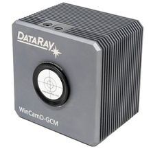
WinCamD-GCM
- GigE Vision supports long cable runs (to 100 m)
- Access your profiler via ethernet network
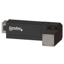
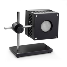
Industrial Laser Monitoring System
- Profile focused, high-power industrial lasers
- Suitable for Gaussian, non-Gaussian, CW, and pulsed beams
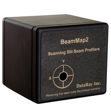
BeamMap2
- Robust, multi-plane beam profiling
- Real-time M², divergence, pointing, and focal measurements