Setting the Right Capture Block
Beam Profiling Concepts | June 20, 2016
Centering the Beam
Centering the laser beam and properly sizing the capture block are important steps in taking accurate laser beam measurements with DataRay software. In this blog post we explain why the beam needs to be centered on the capture block, and the errors that can occur if the corners of the capture block are illuminated by the beam.
DataRay Capture Block and Properly Centering the Beam
The capture block determines which portion of the sensor the software records data from. DataRay software allows a user defined capture block (in the Setup → Capture Setup dialog) with either the whole sensor or a subsection of the sensor. It is important to avoid illuminating the corners of the capture block, so the capture block must be properly sized such that the beam diameter is less than half of the capture block width. Additionally, the beam should be centered on the capture block.
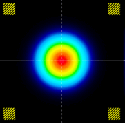
Beam Measurements and Noise Reduction
Although most laser beam measurements with a CMOS or CCD sensor contain noise, generally stemming from ambient light, this noise can be reduced with proper noise reduction algorithms. DataRay’s laser beam profiling software has two main methods for determining the width of a laser beam. The first is the clip level method, which uses a percentage of the maximum intensity to set a clip level. To determine the width, the software calculates the two positions where the beam crosses the clip level and measures the difference. The second method is the ISO 11146 method in which the second moment equations are used to determine the beam diameter. We will address the errors in beam width that occur for the two modes when the corners of the capture block are illuminated.
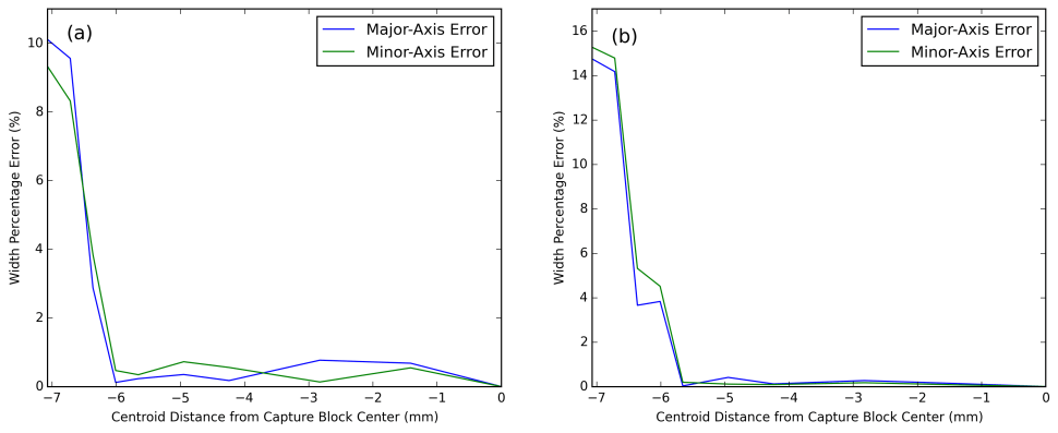
To reduce the effect of noise, the average background noise is subtracted from the data in a process known as baselining, used in both the clip level mode and ISO 11146 mode. To determine the average background noise, a non-illuminated portion of the sensor is needed. DataRay software uses four small pixel arrays in the four corners of the capture block to calculate the mean and standard deviation of the background noise. However, if the corners of the capture block (and consequently the small pixel arrays) are illuminated with the laser beam, then the calculated mean (baseline) and standard deviation include not only the background noise, but also the beam itself. It follows that the mean and standard deviation are larger when the corners are illuminated with the laser beam. With an artificially high baseline—due to the beam in the corner of the capture block—the actual beam is truncated and the calculated width will be smaller. Therefore, the accuracy of the beam measurement is compromised when any of the four corners of the capture block are illuminated.
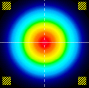
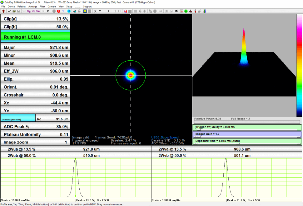
In addition to baselining, the ISO 11146 method also uses thresholding. In ISO 11146 mode, the second moment is used to determine the beam diameter. However, before calculating the second moment, the illuminated pixels are separated from the unilluminated pixels in a process known as thresholding. To determine which pixels are illuminated and which pixels are unilluminated, the software calculates the threshold level by multiplying the standard deviation of the noise by some scalar between 2 and 4. If the pixel value is greater than the threshold level, then the pixel is considered illuminated. However, if the pixel value is less than the threshold level it is considered unilluminated and not used in any further calculations. When the beam illuminates the corner/corners of the capture block, the standard deviation becomes artificially high as does the threshold level. Therefore, many of the pixels that are actually illuminated by the beam fall below the threshold level and are considered unilluminated. The edges of the beam are further truncated and the resulting beam diameter calculation will be erroneous.
Experiment
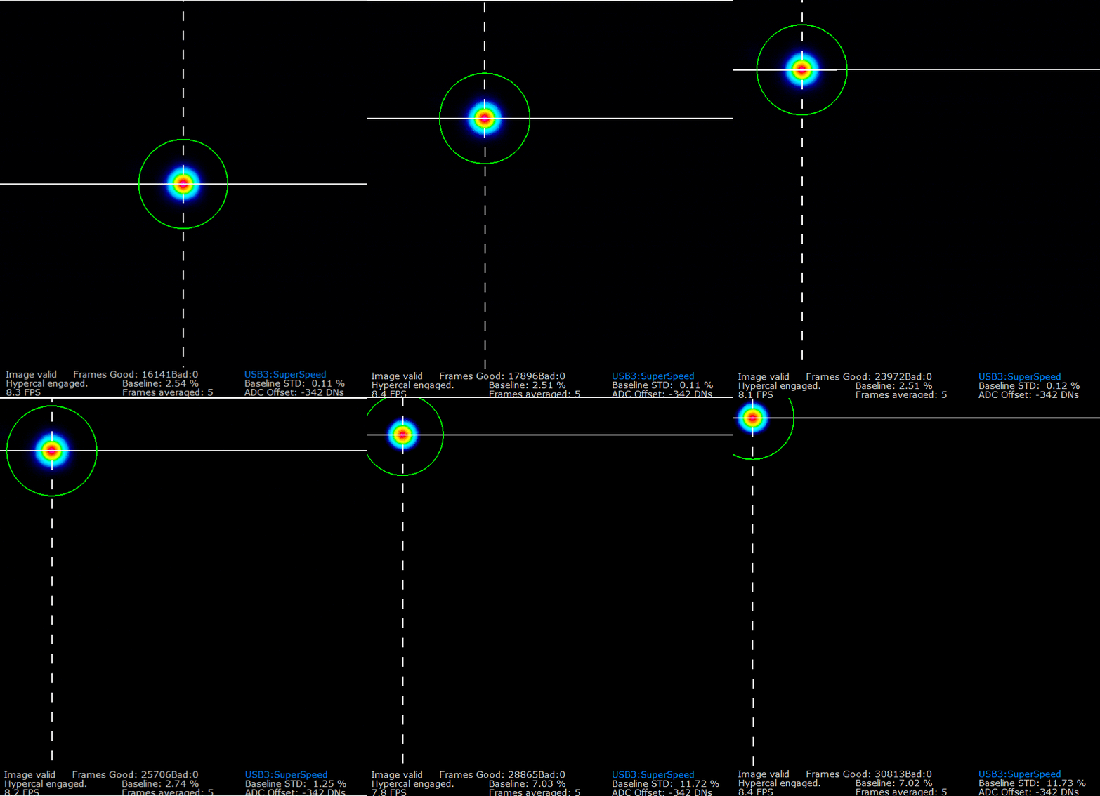
We designed an experiment to test the effect of moving the beam into the corners of the capture block. With a laser source attached to an adjustable mount, we were able to determine with a high degree of accuracy the position of the beam on the WinCamD-LCM image sensor. We moved the beam incrementally from the center of the capture block all the way to the upper left hand corner of the capture block. At each step, the beam diameter—in both clip level mode and ISO mode—was recorded along the major and minor axes. As predicted, the calculated beam diameter became substantially smaller in the corners of the capture block. Additionally, the calculated beam diameter was smaller for the ISO mode than the clip level mode, since the ISO 11146 method has not only baselining error, but also thresholding error.
Conclusion
Properly sizing the capture block and centering the beam within the defined capture block will affect the accuracy of laser beam measurements. For a full list of DataRay’s cameras—which use our proprietary beam profiling software—visit our website. If you have any questions about beam profiling, please contact us.
Author: Lucas Hofer
Related News
Video: Strip Charts
DataRay Software | January 8, 2026
The DataRay beam profiling software provides powerful state-of-the-art features to characterize your beams quickly and efficiently. Our team has developed a series of short videos to help explain and demonstrate key software functionality. This final video in the series covers DataRay’s strip chart feature...
