Introduction
Profiling large laser beams is a common industry need, one with many challenges. What is small to one researcher may be quite large to another. For example, the diameter of a "large" beam may be a relatively small 5 mm, or up to tens of millimeters or larger. Fortunately, DataRay offers several solutions for measuring large beam profiles; these include both direct measurements and indirect measurements employing external optics for beam reduction or remote reimaging. In this article, we will present some of these solutions and describe the factors that must be considered when selecting the best laser beam profiler for your application. Specifically, the four options we will review are: direct beam profile measurement, optical fiber tapers, beam reducers, and reimaging a screen using an ancillary lens.
Direct Beam Profile Measurement
Direct measurement of the beam profile with a camera has the following advantages:
- Fast setup – begin measuring laser beam profiles immediately
- Highest resolution of all discussed methods
- No external optical distortions introduced
When possible, a direct measurement system is quicker and more accurate than using external optics that require alignment and calibration. One product well-suited to direct measurement of large laser beam profiles is DataRay's new large area, high resolution, USB 3.0 CMOS beam profiling camera, the WinCamD-LCM. This camera has 2048 x 2048 pixels, a pixel size of 5.5 µm, and sensor active dimensions of 11.3 x 11.3 mm.
Sensor Active Area Versus Beam Diameter
When selecting a system to measure beams, a key factor is the sensor size. A perfectly Gaussian beam will not require as large a sensor as a non-Gaussian beam. For good-quality Gaussian beams, a good rule of thumb is to limit the beam size to around two thirds of the sensor’s smallest dimension; e.g., a 5 mm array should only be used to measure beams up to around 3.5 mm, an 11.3 mm sensor should be limited to beams below around 7.5 mm, etc.
External Optical Reduction of Large Beams
DataRay also offers several indirect measurement solutions involving beam reduction optics. Once the actual magnification has been calibrated and entered, screen readout dimensions are for the original beam.
Optical Fiber Tapers
DataRay's largest-area camera, the TaperCamD20-15-UCD23, employs a coherent fiber optic taper bundle with an entrance aperture of 20 x 15 mm, and an effective pixel size of 15 µm. The taper's magnification factor is pre-set at the factory in the camera's embedded memory using DataRay’s PMF compensation settings in order to minimize optical distortion.
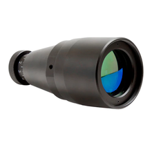
Galilean Beam Reducers
We offer multiple optical beam reducers, handling three wavelength ranges (350-650 nm, 650-1050 nm, and 1050-1620 nm), with various reduction factors:
- BR-X-2 – 1/2 reduction factor, 13 mm aperture
- BR-X-5 – 1/5 reduction factor, 20 mm aperture
- BR-X-10 – 1/10 reduction factor, 30 mm aperture
- BR-X-15 – 1/15 reduction factor, 45 mm aperture
Reimaging a Screen Using an Ancillary Lens
Used with a fixed focal length lens, beam profiling cameras can reimage a laser-illuminated screen onto the CCD or CMOS sensors. Typically, such lenses include a manual iris which simplifies setting the correct illumination level.
This approach, using a beam profiling camera along with an ancillary lens, offers several advantages including:
- Profile large laser beams to >700 mm diameter at a distance of 0.2-1.0 meters
- Profile high-powered beams without expensive attenuators
- Quick and simple setup and calibration achieved by entering the measured magnification into the DataRay software

Measuring and Compensating for Lens Magnification
DataRay's software can compensate for known magnifications and de-magnifications, which can be manually specified in the camera setup options in the software. To calculate this factor, one must move the camera and lens a known transverse distance and measure the transverse change in the position of the image centroid on the screen; e.g., if one moved the camera transversely 10 mm and observed a image centroid moves 400 µm, magnification would be calculated as (0.4/10) = 0.04. By entering 0.04 as the Magnification Factor in the software, the on-screen dimensions would then be calculated correctly.
Speckle reduction
Any static screen will show speckle, typically giving intensity modulation around ±20% and significantly affecting the accuracy of diameter measurement. Some relief can be had by using the linear and area filters in the DataRay software's Filter menu. Even better, the use of a rapidly rotating screen (e.g., white laminate) will help ensure speckle averaging.
DataRay is available to discuss these options for you to assist in the selection of the best system for your needs. Please contact us at [email protected].
Products Mentioned

WinCamD-LCM
- Versatile global shutter supports CW & pulsed beams
- 355 to 1150 nm standard with UV, 1310 nm, and 1550 nm options

TaperCamD-LCM
- Large 25 x 25 mm active area
- Suitable for large beam profiling
Related News
Large Beam Profiling System
Specialized Beam Profiling Systems | July 7, 2016
Although most laser beams can be imaged directly onto an image sensor, occasionally our customers need to measure beams which require a larger sensor area. For beams too large for traditional approaches, DataRay is pleased to announce our new Large Beam Measurement System (LBMS). Read on to learn more!
DataRay Inc. Announces TaperCamD-LCM Large Area CMOS Beam Profiler
Press Releases | January 28, 2019
DataRay Inc., the worldwide leader in laser beam profiling and analysis, is pleased to announce the availability of the new TaperCamD-LCM large area CMOS beam profiler.