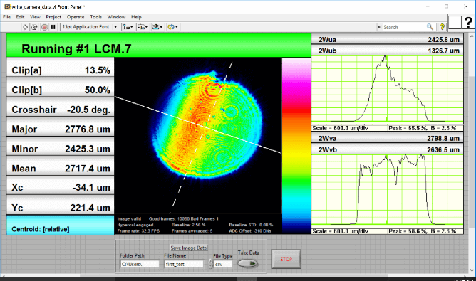
We are pleased to announce a new LabVIEW interface tutorial for both our WinCamD image profilers and BeamMap2 scanning slit profilers. The interface tutorial includes new LabVIEW interface examples which can easily be modified to suit a great variety of applications.
LabVIEW is the program of choice in many research laboratories and industrial systems because of its ability to deftly control hardware from a variety of vendors such as DataRay and National Instruments. In addition to the new LabVIEW interface tutorial and examples, we have increased our support and now include LabVIEW 2015 in our list of supported LabVIEW versions. LabVIEW 2015 is the latest LabVIEW software edition and provides new functionality for LabVIEW programming.
At DataRay, we recognize the place LabVIEW has in both industry and academia and thus work to provide both excellent support and relevant LabVIEW laser beam profiling examples for our customers. In this LabVIEW support tutorial, we demonstrate how to properly interface with either WinCamD series cameras or a BeamMap2 scanning slit device with LabVIEW 8.5 through LabVIEW 2015.
We have provided four new LabVIEW example VIs to assist our customers in adding DataRay laser beam profilers to their existing LabVIEW system. The first three examples VIs are for our popular WinCamD series beam profilers. They explain how to use the ActiveX controls to create a visuassal representation of the camera data and how to acquire various types of data from the camera. The fourth VI example is for our patented BeamMap2 scanning slit profiler with instant M² calculation capability and, in the example, we show how to display various beam images as well as how to acquire both axis and calculation data.
WinCamD Example VIs
The first VI, the WinCamD Camera example, demonstrates how to return and acquire 2D image data from the WinCamD series image profilers. Image profiling, in which the laser beam is incident on a camera sensor (CCD, CMOS or Si Microbolometer), is used to obtain the most accurate 2D profile of a laser beam. Since the camera sensor has a 2D array of pixels, the full beam can be imaged as long as the beam falls completely within the sensor area and the beam width is greater than 10 camera pixels (to provide sufficient beam resolution). The intensity of the beam at each pixel is used in conjunction with DataRay's beam calculation algorithms to return ISO 11146 compliant laser beam analysis. However, the user may wish to perform their own image data analysis and thus, the VI example demonstrates how to acquire the 2D image data from the WinCamD through LabVIEW. This data can be either recorded or used for real-time image analysis and adjustment.
The second VI, the WinCamD Button example, acquires image analysis data calculated by DataRay software. Although the WinCamD image data may be independently analyzed by the user, DataRay provides ISO 11146 compliant calculations (e.g. the centroid position, major and minor axis lengths, ellipticity) to simplify image analysis. In the DataRay standalone application, these calculations are placed in various button panels and the WinCamD Button example explains how to retrieve the calculation data from these button panels with LabVIEW. This data can be recorded as shown in the example or used to perform further calculations.
The third VI, the WinCamD event example, demonstrates how to perform an action when a new frame of data becomes available. The WinCamD Camera example and WinCamD Button example acquire data either at the user's request or at user specified intervals (e.g. 500 ms). However, our customers often find event-driven data acquisition useful because it allows them to do tasks more efficiently. With the WinCamD Event example, we are pleased to demonstrate how to acquire WinCamD data triggered by the DataReady OCX event. When the camera has acquired a new frame of data, the DataReady event is triggered. In LabVIEW a callback VI can be assigned to take an action every time the event is triggered such as recording or analyzing data. This example shows how to use the event to record button panel data. However, the example VI can be modified to record the 2D image array, or perform any other event-driven action.
BeamMap2 Example VI
The fourth VI, the BeamMap2 example, shows how to acquire data from an axis profile as well as open the M² and Divergence dialog boxes. Although image profiling is useful in returning 2D data, scanning slit beam profilers are able to image smaller beams. Additionally, the BeamMap2 uses a patented design to simultaneously obtain scanning slit measurements at multiple locations along the axis of propagation (measurements are the beam profile along the orthogonal u and v axes). Although an ISO 11146 compliant M² calculation requires measurement of the laser beam at ten locations along the axis of beam propagation, the BeamMap2 provides an instantaneous approximation of M² by measuring the beam at four locations along the axis of propagation. This M² measurement provides enough accuracy for many applications. The BeamMap2 LabVIEW example demonstrates how to acquire the laser profile from either the u or v axis at one of the four measured positions (2 axes x 4 positions = 8 total axis measurements). Additionally, this LabVIEW example VI shows how to open the M² and Divergence dialog boxes which provide detailed information and graphs pertaining to M² and the Divergence.
Application Note
An Application Note related to the topic described about is available for review here.
Additional information on interfacing DataRay laser beam profilers as well as full documentation of the DataRay OCX is provided. Additionally, we would love to talk with you about adding DataRay beam profilers to your existing LabVIEW system. Should you have any questions about interfacing LabVIEW, feel free to contact us.


